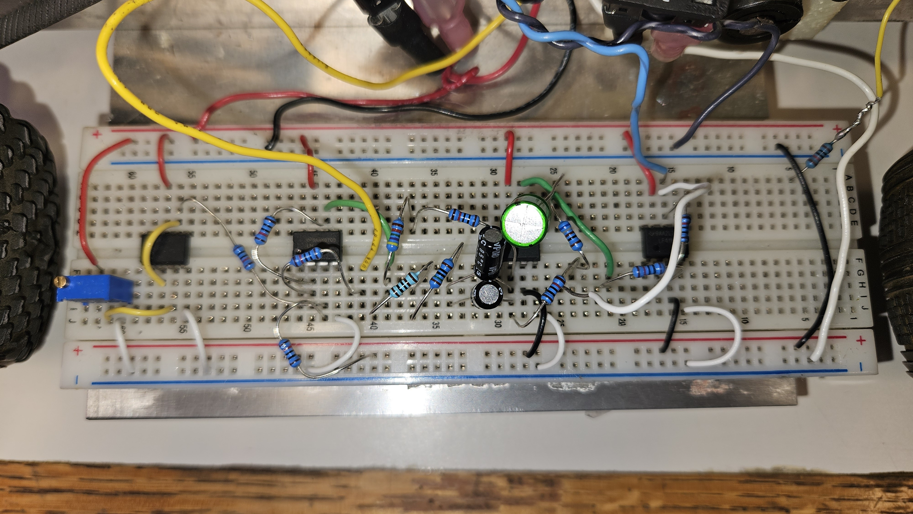
Final implemented compensator design on a breadboard including resistors, capacitors and op-amps.
An inverted pendulum is an inherently unstable system. The pendulum is free to rotate in one axis (forward or backward), while the car it is attached to must keep it balanced by using its own motion to counteract the falling pendulum.
I worked with a partner as part of our final project for ENGS 26: Control Theory to develop a compensator to process sensor input corresponding to the pendulum angle and output appropriate control signals to the motor. We first derived a mathematical model for the system from first principles and designed experiments to determine the appropriate values for our particular car. Part of this model is shown below.
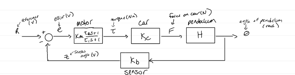
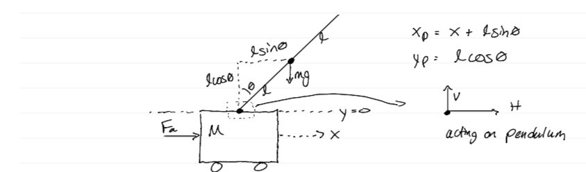
After analyzing the root locus and bode plot of the uncompensated system, we designed a PID compensator with a stop resistor to meet settling time specifications and keep control effort under the maximum 12 volts the battery could supply.
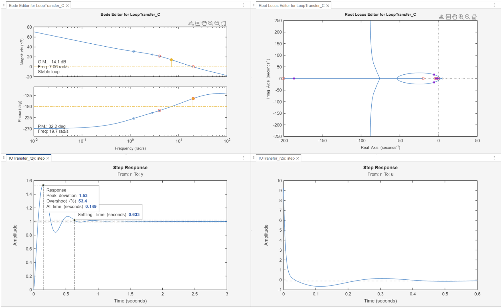
Designed PID controller with stop resistor simulated in MATLAB to stabilize the system. This design was further improved through experimental tuning later.
Ultimately, we implemented this design on a circuit board with resistors, capacitors, and op-amps and tuned it to improve the final experimental specifications. After tuning, we reduced settling time to only 0.213 seconds with zero steady-state error without violating control effort constraints.